Fixed Ball Valve Manufacturing Process Explained: Complete Guide
Fixed Ball Valve Manufacturing Process Explained (Complete Guide)
This comprehensive guide explains the fixed ball valve manufacturing process step by step.
It covers design, material selection, machining, assembly, testing, and quality control for
industrial fixed ball valves, also known as trunnion mounted ball valves. The content is
neutral, industry-standard, and suitable for use on blogs, directory pages, and engineering
resource pages.
1. What Is a Fixed Ball Valve?
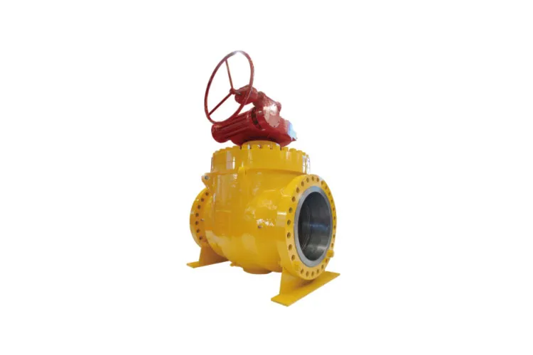
A fixed ball valve, commonly called a trunnion mounted ball valve,
is a quarter-turn shut-off valve where the ball is held firmly in place by mechanical supports
called trunnions. Unlike a Floating ball valve, the ball in a fixed ball valve does not
move downstream under pressure. Instead, the seats are spring loaded or pressure energized to
maintain tight sealing against the fixed ball.
Fixed ball valves are widely used in high-pressure and large-diameter pipeline systems for oil, gas,
petrochemical, power generation, and industrial process applications. They are designed for
reliable tight shut-off, low operating torque, and long service life under demanding conditions.
1.1 Key Characteristics of Fixed Ball Valves
- Ball is supported by upper and lower trunnions (fixed ball design).
- Seats are spring loaded or pressure assisted to achieve sealing.
- Lower operating torque than floating ball valves in large sizes.
- Suitable for high pressure classes (e.g., Class 600, 900, 1500 and above).
- Common design standards: API 6D, API 608, ISO 17292, ASME B16.34.
- Available in soft-seated and metal-seated configurations.
1.2 Fixed Ball Valve vs. Floating Ball Valve
Feature |
Fixed (Trunnion Mounted) Ball Valve |
Floating Ball Valve |
Ball Support |
Ball is supported by trunnions at top and bottom |
Ball is held by seats and stem; can float slightly downstream |
Seat Movement |
Seats move towards the fixed ball to seal |
Ball moves against the downstream seat to seal |
Typical Size Range |
Preferable for medium to large diameters (e.g., DN50 and above) |
Common in small to medium diameters (e.g., DN15–DN200) |
Operating Torque |
Lower torque, suitable for high-pressure and large-bore service |
Higher torque as pressure increases |
Applications |
Pipeline isolation, transmission lines, high-pressure service |
General service, low to medium pressure applications |
Cost |
Generally higher due to more complex construction |
Typically lower for small sizes and low pressures |
2. Typical Applications of Fixed Ball Valves
Fixed ball valves are widely selected where safety, reliability, and tight shut-off are critical.
Common industrial applications include:
- Crude oil and refined product pipelines
- Natural gas transmission and distribution networks
- Petrochemical process plants and refineries
- Offshore and onshore production facilities
- Underground storage and tank farms
- Power generation cooling water and steam isolation
- High-pressure chemical and utility systems
3. Advantages of Fixed Ball Valves
The fixed ball design offers several performance and maintenance advantages in demanding
industrial environments. These advantages explain why fixed ball valves are the preferred
choice for critical pipeline isolation.
3.1 Main Advantages
-
Lower Operating Torque – Because the ball is supported by trunnions,
the contact forces between the ball and seats are reduced, resulting in lower turning torque.
This simplifies actuation and reduces actuator size.
-
Improved Sealing at High Pressure – Spring-loaded or pressure-energized
seats move towards the ball, maintaining consistent sealing even with pressure fluctuations
or temperature changes.
-
Better for Large Sizes – The fixed ball design is mechanically stable for
large diameters, preventing ball deformation and seat damage under pipeline loads.
-
Long Service Life – Even distribution of loads and robust bearing / trunnion
support contribute to extended service life in frequent operation or harsh conditions.
-
Double Block and Bleed Capability – Many fixed ball valves are designed
for double block and bleed (DBB) service, enabling reliable isolation and cavity venting.
-
Fire-Safe Design Options – Fire-safe certified fixed ball valves can maintain
sealing capability after exposure to fire, using metal-to-metal backup seats.
4. Design, Materials, and Standards for Fixed Ball Valves
4.1 Common Design Standards
Fixed ball valves are designed in accordance with internationally recognized industrial
standards. Typical references include:
- API 6D – Specification for Pipeline Valves
- API 608 – Metal Ball Valves, Flanged, Threaded and Welding Ends
- ISO 17292 – Metal Ball Valves for the Petroleum, Petrochemical and Allied Industries
- ASME B16.34 – Valves – Flanged, Threaded and Welding End
- ASME B16.5 / B16.47 – Flange dimensions for end connections
- API 607 / ISO 10497 – Fire Test for Valves
- ISO 15848 – Industrial Valves – Fugitive Emissions
4.2 Typical Materials for Fixed Ball Valves
The selection of body, ball, seat, and trim materials depends on pressure, temperature,
medium, and corrosion requirements. Common material choices include:
Component |
Common Materials |
Typical Use |
Body & Bonnet |
Carbon steel (A216 WCB, A105), low alloy steel, stainless steel (CF8M, CF3M), duplex stainless steel |
General pipeline service, high-pressure and corrosive media |
Ball |
Stainless steel, chrome-plated carbon steel, tungsten carbide coated alloy, Inconel overlay |
Wear resistance, corrosion resistance, erosion resistance |
Seats |
PTFE, reinforced PTFE, PEEK, nylon, metal (Stellite, hardfacing alloys) |
Soft sealing for standard service, metal seated for high temperature or abrasive media |
Stem |
Stainless steel, alloy steel, nitrided or surface-hardened materials |
High strength, resistance to corrosion and galling |
Seals & Gaskets |
PTFE, graphite, elastomers (Viton, NBR, EPDM) |
Body joint sealing, stem packing, seat energizing |
Trunnions & Bearings |
Alloy steel, stainless steel, self-lubricating bearings |
Support for the fixed ball, low friction operation |
4.3 Typical Pressure and Temperature Ratings
Fixed ball valves are commonly available in the following pressure and temperature ranges:
- Pressure ratings: ASME Class 150 to Class 2500 (and equivalent PN classes).
- Temperature range: approximately -46°C to +400°C (depending on materials and seat design).
- End connections: flanged, butt weld, socket weld, and sometimes threaded ends for smaller sizes.
5. Fixed Ball Valve Manufacturing Process Overview
The manufacturing process of a fixed ball valve is a controlled sequence of design,
material procurement, machining, welding, heat treatment, assembly, testing, and inspection.
Every step is documented and traceable to ensure compliance with customer specifications and
industry standards.
The main stages in the fixed ball valve manufacturing process include:
- Engineering design and specification review
- Material selection and procurement
- Casting or forging of body, ball, and major components
- Heat treatment and stress relief
- Precision machining of body, ball, seats, and stems
- Surface treatment, coating, and overlay (if required)
- Cleaning, deburring, and dimensional inspection
- Valve assembly (ball, trunnions, seats, stem, seals)
- Pressure testing (shell test, seat leakage test, functional test)
- Painting, marking, and final documentation
- Packing and shipping
5.1 Process Flow Table
Step |
Process |
Main Purpose |
1 |
Design & Engineering |
Define dimensions, pressure rating, materials, and standards |
2 |
Material Procurement |
Obtain certified raw materials for body, ball, and trims |
3 |
Casting / Forging |
Form body, bonnet, ball blanks, and major parts |
4 |
Heat Treatment |
Achieve required mechanical properties and relieve stress |
5 |
Machining |
Finish critical dimensions, sealing surfaces, and tolerances |
6 |
Surface Treatment & Coating |
Improve corrosion, wear, and abrasion resistance |
7 |
Cleaning & Inspection |
Remove contaminants and verify dimensions and quality |
8 |
Assembly |
Install ball, trunnions, seats, stem, packing, and seals |
9 |
Testing |
Hydrostatic and functional tests for sealing and performance |
10 |
Painting & Marking |
Apply coating and identification for service and traceability |
11 |
Packing & Shipping |
Protect the fixed ball valve during transport and storage |
6. Design and Engineering Stage
The manufacturing of a fixed ball valve starts from the design and engineering stage. At this step,
technical requirements, pipeline conditions, and project specifications are translated into
detailed valve designs and manufacturing documents.
6.1 Design Inputs
- Design pressure and design temperature
- Service medium (oil, gas, water, chemical, slurry, etc.)
- Pipe size, schedule, and end connection requirements
- Applicable industry standards (e.g., API 6D, ASME B16.34)
- Special requirements such as fire-safe, anti-static, low emission, and double block and bleed
- Actuation mode (manual, gear, pneumatic, electric, hydraulic)
6.2 Engineering Activities
- Valve sizing and bore selection (full bore or reduced bore)
- Finite element analysis (FEA) for stress and pressure integrity
- Flow analysis and torque calculation
- Preparation of general arrangement drawings and bill of materials
- Development of manufacturing and inspection plans
7. Material Selection and Procurement
After the design is finalized, material selection and procurement take place. Raw materials must
meet mechanical, chemical, and corrosion requirements defined by standards and project
specifications.
7.1 Material Certification
Raw materials for fixed ball valves are typically supplied with material test reports (MTRs) or
mill test certificates, including:
- Chemical composition
- Mechanical properties (yield strength, tensile strength, elongation)
- Heat treatment condition
- Heat number and traceability information
7.2 Typical Materials for Different Pressure Classes
Pressure Class |
Body Material |
Ball & Stem Material |
Typical Service |
Class 150–300 |
Carbon steel, stainless steel |
Stainless steel or alloy steel |
General oil, gas, and water pipelines |
Class 600–900 |
Low alloy steel, high-grade carbon steel, stainless steel |
High-strength stainless or alloy steel |
High-pressure transmission lines |
Class 1500–2500 |
High strength alloy steel, special stainless steels |
High-alloy or coated components |
Severe service, critical isolation, high temperature |
8. Casting and Forging of Major Components
The body, bonnet, and ball of a fixed ball valve are typically produced using high-quality
castings or forgings, depending on pressure rating and material requirements.
8.1 Casting Process
For many carbon steel and stainless steel fixed ball valves, the body and bonnet are produced
by sand casting or investment casting:
- Pattern and mold preparation
- Melting of metal and chemical composition control
- Pouring into molds and solidification
- Shakeout, riser removal, and cleaning
- Visual inspection and non-destructive testing (e.g., radiography, magnetic particle test)
8.2 Forging Process
For high-pressure fixed ball valves, forgings are often preferred due to superior mechanical
properties and grain structure:
- Cutting of billets from certified material bars
- Heating to forging temperature
- Open die or closed die forging of body and ball preforms
- Trimming, normalizing, and conditioning
- Preliminary machining and inspection
8.3 NDT and Inspection of Castings and Forgings
Before machining, cast or forged components for fixed ball valves undergo non-destructive testing:
- Visual and dimensional inspection
- Radiographic testing (RT) for internal defects
- Ultrasonic testing (UT) for internal discontinuities
- Magnetic particle testing (MT) or dye penetrant testing (PT) for surface defects
9. Heat Treatment and Stress Relief
Heat treatment is used to achieve required mechanical properties and relieve residual stresses
after casting or forging. Typical heat treatment processes for fixed ball valve components
include:
- Normalizing
- Quenching and tempering
- Solution annealing for stainless steels
- Stress relieving after welding or heavy machining
Heat treatment cycles are recorded and linked to material heat numbers for full traceability in
the fixed ball valve manufacturing process.
10. Precision Machining of Fixed Ball Valve Components
Precision machining is one of the most critical steps in the fixed ball valve manufacturing
process. Accurate dimensions and fine surface finishes are essential for tight sealing and
low operating torque.
10.1 Body Machining
- Boring of flow passage and cavity
- Machining of end flanges or welding bevels
- Machining of seat pockets
- Stem hole and trunnion bearing seat machining
- Drilling and tapping of body-to-bonnet bolt holes
- Finish machining of gasket sealing faces
10.2 Ball Machining
For a fixed ball valve, the ball must have excellent roundness and surface finish. Typical
ball machining operations include:
- Rough turning of ball blanks
- Finish turning and boring of flow port
- Grinding and lapping of spherical surface
- Finishing of trunnion and stem connection features
For severe service fixed ball valves, the ball may receive hard coatings such as chrome plating,
tungsten carbide, or stellite to improve wear and erosion resistance.
10.3 Seat and Stem Machining
- Machining of seat rings to precise OD/ID and sealing surfaces
- Grooving for soft inserts and o-rings
- Stem turning, milling of keyways or stem flats
- Threading for stem nut or actuator interfaces
10.4 Machining Tolerances
Typical machining tolerances for critical sealing and guiding surfaces in a fixed ball valve
are in the range of micrometers. Surface roughness is controlled to ensure low friction and
reliable sealing. A simplified tolerance example is shown below (for illustration only):
Component |
Critical Feature |
Typical Tolerance (Example) |
Surface Roughness (Ra) |
Ball |
Spherical outside diameter |
±0.02 mm |
≤ 0.2 μm |
Seat Ring |
Sealing surface |
±0.03 mm |
≤ 0.4 μm |
Body |
Seat pocket diameter |
±0.05 mm |
≤ 1.6 μm |
Stem |
Packing area cylindrical surface |
±0.02 mm |
≤ 0.4 μm |
11. Surface Treatment and Coating
Surface treatment improves the corrosion resistance, wear resistance, and operational life of
fixed ball valves, especially in aggressive operating environments.
11.1 Common Surface Treatments
- Internal coatings – Epoxy, phenolic, or other protective coatings for corrosive media.
- External coatings – Primer and topcoat painting systems for weather and corrosion protection.
- Hardfacing – Stellite or similar hard alloys on seat rings and sealing surfaces.
- Ball coatings – Chrome plating, tungsten carbide HVOF coating, or nitriding for increased durability.
Coating thickness, adhesion, and coverage are inspected according to specified standards and
project requirements.
12. Cleaning, Deburring, and Dimensional Inspection
Before assembly, all components of the fixed ball valve must be clean and free of sharp edges
or contaminants that could affect sealing or operational performance.
12.1 Cleaning Processes
- Degreasing and removal of machining oils
- Shot blasting or bead blasting of cast surfaces
- Pickling and passivation for stainless steel components
- Flushing of internal passages with clean fluids or air
12.2 Dimensional Inspection
Dimensional inspection ensures that machined components meet drawing requirements. Typical
measurement methods include:
- Calipers, micrometers, and gauges for linear dimensions
- Coordinate measuring machines (CMM) for complex profiles
- Surface roughness testers for sealing surfaces
- Run-out and concentricity measurements for rotating elements
13. Fixed Ball Valve Assembly Process
The assembly stage combines all manufactured components into a complete fixed ball valve
ready for pressure testing. Proper assembly is essential for reliable field performance.
13.1 Preparation for Assembly
- Verification of component identity and conformity to drawings
- Cleaning of all components and assembly areas
- Preparation of tools, fixtures, and lifting equipment
- Verification of lubricants and sealants compatibility with the service medium
13.2 Typical Assembly Steps
- Installation of trunnion bearings in the body.
- Insertion of the fixed ball into the body cavity with care to protect the spherical surface.
- Installation of trunnions (upper and lower) and securing with appropriate hardware.
- Fitting of seat rings with springs, o-rings, and soft inserts (for soft-seated designs).
- Installation of the stem through the top of the ball and engagement with the ball slot.
- Installation of stem seals, packing rings, gland, and gland flange.
- Assembly of bonnet or top entry cover (if applicable), including gaskets and bolts.
- Assembly of end closures, adapter flanges, or fully welded connections as required.
13.3 Torque and Fastening Control
During assembly, bolts and fasteners are tightened to specified torque values, often in a
crisscross pattern, to ensure even gasket loading. This is critical for body-bonnet joints and
seat retainer assemblies in fixed ball valves.
14. Pressure Testing and Functional Testing
Every fixed ball valve undergoes pressure testing before shipment to verify its integrity and
sealing performance. Testing is performed according to relevant standards (such as API 6D, API 598,
or ISO standards) and customer specifications.
14.1 Typical Valve Tests
- Hydrostatic shell test – To check the body and pressure-containing parts for leaks.
- Hydrostatic seat test – To verify sealing between seats and ball.
- Low-pressure air / gas seat test – To detect minor seat leakage at low pressure.
- Functional operation test – To ensure smooth opening and closing and correct torque.
- Fire-safe test (when required) – To verify fire-safe performance to standards such as API 607.
- Fugitive emission test (when required) – To check stem seal leakage.
14.2 Example Hydrostatic Test Parameters
Test Type |
Test Medium |
Test Pressure |
Holding Time |
Acceptance Criteria |
Shell Test |
Water |
1.5 × rated pressure |
As per standard (e.g., 2–15 minutes) |
No visible leakage from body and joints |
Seat Test (High Pressure) |
Water |
1.1 × rated pressure |
As per standard |
Leakage within allowable limits or zero leakage, depending on specification |
Seat Test (Low Pressure) |
Air or nitrogen |
~0.6–0.9 MPa |
As per standard |
No bubbles or detectable leakage |
15. Quality Control and Inspection in Fixed Ball Valve Production
Quality control is integrated throughout the fixed ball valve manufacturing process. Inspection
plans typically define mandatory checkpoints, test procedures, and acceptance criteria.
15.1 Quality Management Elements
- Incoming material inspection and traceability
- In-process inspection during machining and assembly
- Non-destructive examination of welds and castings
- Pressure test witnessing and documentation
- Final visual inspection and marking verification
- Certification according to requested standards
15.2 Typical Inspection Records
- Material test reports (MTR) and heat treatment records
- Dimensional inspection reports
- NDT (RT, UT, MT, PT) reports
- Pressure test certificates
- Coating and painting inspection reports
16. Painting, Marking, and Packing
After successful testing and quality control release, fixed ball valves undergo painting,
marking, and packing.
16.1 Painting and Coating
- Surface preparation (e.g., blasting to specified cleanliness)
- Application of primer and intermediate coats
- Topcoat application for color-coding or environmental protection
16.2 Marking
Fixed ball valves are marked in accordance with applicable standards and project requirements,
including:
- Manufacturer or plant identification (if allowed by the standard)
- Valve size and pressure rating
- Material designation
- Flow direction (if applicable)
- Heat number or traceability codes
- Standard references (e.g., API 6D, ASME B16.34)
16.3 Packing and Preservation
- End protectors or flange covers to prevent damage and contamination
- Desiccants or rust inhibitors for internal protection
- Crating or palletizing to facilitate handling
- Clear labeling for size, weight, and lifting points
17. Typical Technical Specifications for Fixed Ball Valves
The following table summarizes typical technical specifications for industrial fixed ball
valves. Actual values may vary depending on design standards and application requirements.
Parameter |
Typical Range / Options |
Valve Type |
Fixed ball valve (trunnion mounted ball valve) |
Size Range |
DN15 (1/2″) to DN1400 (56″) or larger on request |
Pressure Class |
ASME Class 150–2500, PN10–PN420 |
End Connections |
Flanged (RF, RTJ), butt weld, socket weld, threaded (small sizes) |
Bore Type |
Full bore or reduced bore |
Body Materials |
Carbon steel, low alloy steel, stainless steel, duplex, special alloys |
Ball Materials |
Stainless steel, alloy steel with hard coating, special alloys |
Seat Type |
Soft seated (PTFE, R-PTFE, PEEK, etc.) or metal seated |
Temperature Range |
Approx. -46°C to +400°C (depending on materials and seat design) |
Design Standards |
API 6D, API 608, ISO 17292, ASME B16.34 |
Face-to-Face |
ASME B16.10, API 6D, or ISO standards |
Fire-Safe Design |
Available according to API 607 / ISO 10497 (on request) |
Actuation Options |
Lever, gear operator, pneumatic actuator, electric actuator, hydraulic actuator |
Additional Features |
Double block and bleed, emergency sealant injection, anti-static device, blow-out proof stem |
18. Frequently Asked Questions About Fixed Ball Valve Manufacturing
18.1 Why choose a fixed ball valve instead of a floating ball valve?
A fixed ball valve is preferred for high-pressure, large-diameter, and critical pipeline
applications. The fixed ball design reduces operating torque, enhances sealing stability, and
extends service life. Floating ball valves are typically more economical for small sizes and low
to medium pressures.
18.2 How is leakage class controlled in fixed ball valves?
Leakage class is controlled by precise machining, high-quality seat materials, and careful
assembly. Hydrostatic and pneumatic seat tests are performed to verify leakage performance
against standards such as API 6D, API 598, or ISO 5208. Soft-seated fixed ball valves often
achieve tight shut-off (zero leakage).
18.3 What is double block and bleed in a fixed ball valve?
Double block and bleed (DBB) refers to a design where both upstream and downstream seats can
seal independently, allowing the cavity between them to be bled or vented. Many fixed ball valves
offer DBB capability, providing enhanced isolation and safety for maintenance and inspection.
18.4 What standards cover fire-safe testing of fixed ball valves?
Fire-safe fixed ball valves are tested according to standards such as API 607 or ISO 10497.
These tests expose the valve to fire conditions and verify that sealing performance and pressure
integrity are maintained, using metal backup seats and fire-safe stem packing designs.
19. Conclusion: Understanding the Fixed Ball Valve Manufacturing Process
The fixed ball valve manufacturing process is a detailed and highly controlled sequence covering
design, material selection, casting or forging, precision machining, surface treatment, assembly,
and rigorous testing. Each step is essential to ensure that the finished fixed ball valve
delivers safe, reliable, and long-lasting performance in demanding industrial applications.
By understanding how fixed ball valves are manufactured and what standards they follow, engineers,
buyers, and project managers can make informed decisions when selecting and specifying trunnion
mounted ball valves for oil and gas, petrochemical, power, and general industrial services.
“`






 Phone